LowBrau morphs into a Raspberry Pi brewbot

October 7, 2013

It’s been 4 months since I last wrote about my automated brewing project.  LowBrau was meant to be a low cost single-vessel automated step mash and boiling system.  But, although the controller box was mostly complete, I ran into problems when I fried my Arduino.  That and the hellishly cramped nature of my project box (which was designed to sit neatly under the boiling vessel) really put the brakes on mentally for me – I just wasn’t super motivated to push forward.

Although I may have been silent on this one, I have been working on the next iteration of the project for the last couple of months.  It was always my intention to not simply clone the commercially available systems, but to better them where I see a feature that is clunky or limited.  As a result this hiatus seemed like the perfect opportunity to rethink the core technologies of the project.

The biggest change is that I have now decided to ditch the Arduino and base the control box off a Raspberry Pi.  At $35 this little embedded linux computer is vastly more powerful than an Arduino, yet it really isn’t much more expensive than a name-brand Arduino.  It will allow profoundly enhanced functionality.

I also bought a far bigger project box.  Rather than living under the boiling vessel this one will be fully detachable, with all inputs and outputs connected via sockets.  It can happily live on the bench next to the brewbot.  I divided it into two physical sections with an off-cut of PVC square-section drainpipe to separate the high and low voltage components.

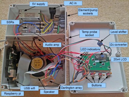
I’ll write a bit of commentary about each main component pictured in the photo below…

PiNT control box

As I wanted the control box fully detachable the AC power comes in and the pump and element connect via IEC sockets.  I went with snap in mountings rather than ones that require bolts/rivets, so all that was needed was an accurately sized rectangular hole to push them through.

The element and pump are switched by solid state relays.  Mine are Fotek 25DA.  I neither recommend or warn you off them – other than to say that they cost less than $4 each including postage and one of them came dead-on-arrival.  They’re mounted onto the heatsink used in the previous edition of the controller box.

Lastly in the high voltage area there’s the 5V 2A power supply module.  Everything else in the box gets powered off this 5V supply.  The RPi requires 1A, so there’s an additional 1A overhead for all the rest of the bits.

Down the left hand side is the Raspberry Pi (RPi).  The 26 pin general purpose input/output (GPIO) connector is connected to my breakout board via some grey ribbon cable.  I have thrown a very cheap $4 USB wifi (rtl8188cus chipset) on the RPi which will allow the advanced interface opportunities.

The temperature probe attaches via a 4 pin socket on the right.  The probe uses the DS18B20 chipset which is read natively by the RPi using the 1-Wire connector on the GPIO.  In linux the output of this probe appears as a text file for easy reading.  Couldn’t be simpler.

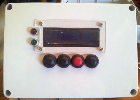
Along with wifi control, I also want to keep the option to control everything through the control box as usual.  I have selected a 20×4 LCD ($5), which provides more screen space than the Braumeister’s 16×2.  This in turn will allow me to implement a more sensible user interface that doesn’t require so many nested menus and laborious button pressing.  The LCD is a standard HD44780 chipset, however I do not connect it straight to the GPIO.  I have soldered to the back an i2c conversion board ($3) which further shrinks the number of IO lines to 2.  It also conveniently takes care of all the contrast potentiometer wiring.  Between this board and the RPi is a level shifter board ($2).  This is necessary because the RPi GPIO all works off 3.3V levels, not the 5V standard.  This board is bi-directional so it pumps 3.3V signals to 5V in one direction and 5V back down to 3.3 in the other.

On a related note, all the other outputs (SSR signals and LED indicators) are passed through a Darlington array (60c).  The 3.3V supply internal to the RPi only has a total capacity of 50mA – so even 3 LEDs would take it beyond its capacity!

The buttons are set with both pull-up resistors and current limiting resistors.  The pull-ups (10k) are required to stop the inputs from floating.  The current limiting resistors (1k) are often left out by people, but they’re a pretty good idea to do it correctly.  If your GPIO is always set up correctly as inputs then you’d never need them, but in the case that they get set erroneously as outputs they prevent them from creating a short circuit between the RPi output and ground.  I have also installed 100nF ceramic capacitors across the terminals of the buttons to hardware debounce them.  A quick circuit diagram is below.

PullUp-SwitchProtected-DebouncedAnd finally, there’s a speaker and amplifier.  One of the annoyances I find with the Braumeister is the incessant beeping that seems to accompany almost every step of the process.  Yet despite this it can also be surprisingly unapparent when everything has stopped waiting for you to press a button.  I have decided to solve these problems by replacing the buzzer in favour of voice prompts driven off the RPi audio output.  While a flashing status LED will give clear indication that a user input is needed.  The amp is a 5V D-class 3W audio amplifier ($3), which is commonly used in USB speakers and for that reason conveniently runs off my 5V supply and is plenty loud enough.

LowBrau – Setbacks and Delay

May 27, 2013

Anyone who has been following the progress on the LowBrau project would have seen a whole flurry of activity followed by a long period of silence.  Within 4 days of starting I had got to the stage where the case was drilled and filed for all components; the screen, buttons, LED indicators, temperature probe socket, buzzer, arduino and wiring shield were wired and mounted; the screen protector made and adhered with waterproof silicone caulk; and the SSRs and heatsink mated, mounted and wired up.

Pretty much everything was complete and ready for a test run.  And indeed I did, uploading my control software to the arduino, powering it off USB and everything ran as it should from menus to button presses, etc.  Excellent – all that remains is to remove the USB power and power it stand-alone off its own power supply.

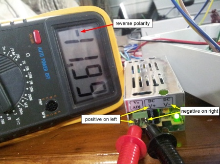
This is where my cheap ebay power supply vendor threw a spanner in the works.  In a break from character I didn’t power it up and throw my multimeter over it before installing it in the LowBrau controller.  Unfortunately for me I was unaware that this power supply has been incorrectly labelled (the sticker placed upside-down).

lowbrau - ebaypowersupply_reversepolarity

I am also quite surprised that arduinos (especially being aimed at the hobbyist market) do not feature a diode to protect against a reverse polarity situation.  Incorrect supply wiring will instantly destroy an arduino, which is exactly what happened to mine.

Annoyingly the arduino cost far more than the power supply that took it out.  And without a spare I had to wait for a replacement and in the intervening time I lost momentum with it all.  But I still have plans to get back onto it in the future.

So if there was ever an encouragement to embrace the inner-pedant and check everything yourself, irrespective of what the manufacturer has written, then this is it!


LowBrau – Screen Protector

March 8, 2013

I am trying to keep the controller box as water-tight as possible.  Although I don’t expect it to be hosed down, I can see that with an inherently liquid-based enterprise it is entirely foreseeable that it’s likely to get the odd splash.  At the moment the LCD module simply pokes through a hole in the box, so it needs some sort of cover to seal it all up (as well as provide some knock protection).

All I really want is a rectangle of thin clear plastic.  So I went looking for some trash that could be repurposed.  My first attempt was using an old CD cover.  This proved too flimsy – once the edges were removed it was quite floppy.  In the end I used the plastic from a box of ex-Christmas Ferrero Roche.  I’m sure that an old iPod/iPhone box would work even better (not that I have many of them lying around).

The best way to work the material is to rough cut the sides off to leave a single flat sheet of plastic.  A hacksaw or Dremel cutting wheel works well for this.  To actually cut the final edges of the rectangle (ie the fine work) the best approach is one similar to glass cutting.  Score your line a few times with a craft knife and straight-edge.  The bend to snap along the score line with some flat-nosed pliers.

lowbrau - screen protector cutting

This way the rough stock can be made properly square (as in, given proper 90 degree corners) and the results are quite accurate, straight sides.  Any jagged edges can be knocked back to smooth with a light sanding.

Then all is needed are a few holes for mounting screws and (later) a little silicone sealant.

lowbrau - screen protector installed

As you can see in the photo above, my box has a little dot imperfection where the injection molding has taken place.  I may end up sourcing a better piece of stock and remake using this one as a template.  If that were to happen this would actually be a very quick operation to duplicate the two (this one took about 5 minutes to make).  Or I may just live with what I have…


LowBrau – Low Voltage Wiring

March 6, 2013

Now that the major components have been fitted to the front and back halves of the controller box it’s time to start wiring up the low voltage components.

lowbrau - low voltage wiring front

I started by installing an earth wire (green) to the LED bezels – as any conductive surfaces on the exterior of the box should be properly earthed.  Next the cathodes of the LEDs were bent together and soldered in place with a ground wire (black).  Each anode then got its own signal wire (orange).

Next the navigation buttons received their common ground (black) and individual signal wires (white/grey).  Each signal wire not only connects to an input pin on the arduino, but also connects to the 5V rail via a 10k pull-up resistor.  This circuitry, however, I will deal with soldered directly on the proto-board.

After this my LCD needed its leads, so I soldered together the connections in the pin header sockets using red for 5V, black for ground and yellow for data lines.

lowbrau - low voltage wiring back

On the back panel the SSRs need their signals and common ground.  As the signal that triggers the SSR is physically the same pin that lights the respective LED I chose to use orange for these lines too.

All these various lines then connect each component to the arduino via a shield made from prototyping board.  I took strips of pin header and pushed the pins all the way through their black plastic strip so that I could keep the solder side towards the arduino.  Unfortunately the second bank of digital connections (data lines 8 to 13) are not aligned with the grid of the proto-board, so they need to sit on their own little board.  This is a slightly annoying feature of the way that the arduino has been designed – and the cynic in me wonders if it’s to create a market for people buying prototyping shields!

lowbrau - pcb

The main items that live on the circuit board are 5V, 12v and ground buses; the button pull-up resistors; the LCD contrast trim-pot and the buzzer transistor.  As a result, none of the circuitry is mind-boggling complex and a custom printed PCB is an unnecessary expense (although it would make for a far quicker job).

Once all this wiring had been completed it was time to flash the arduino and see if it all works.  And success!

lowbrau - lcd first run

Currently the LCD, navigation buttons, and LEDs are fully functional.  There are header pins for the SSR signal wires to plug into (allowing both halves of the box to split apart) and the transistor for the buzzer needs to go in.  My temperature probe has not arrived yet, so that only has some loose wires (purple) awaiting it.


LowBrau – Front Panel Hardware

March 5, 2013

After mounting the SSRs and heatsink to the rear half of the waterproof control box, I figured I’d plough on and fit all the front panel hardware.  As such this post doesn’t really have a lot of earth-shattering content, but I will run down a few of the items that make up this part of the build.

lowbrau - front panel inside

The green circuit board in the centre is the liquid crystal display which will provide the main interface for the user.  This module is a common HD47780 ($2.40) which is easy to interface with digital circuits – indeed arduino has a library specifically written to do just that, you simply need to specify which pins you have connected each of the LCD terminals to and away it goes.  I soldered some header pins on so that I can easily disconnect it from the rest of the controller wiring, should I need to.  I will need to work out how to protect the screen from knocks and liquid splashes, but that’s a challenge for another day.

Beneath the LCD sit four control buttons.  These provide the navigation inputs to allow the user to control the LCD.  I chose waterproof buttons, which don’t seem to be widely available cheaply so these ended up being close to $5 each!  Feels a little unreasonable but cannot be helped.

To the immediate right of the LCD are two LED indicators.  These will serve to provide a visual indication of the state of each output relay (ie whether or not the pump or heating element is switched on).  This might prove important in avoiding accidentally leaving the heating element on while the brew vessel is empty.

On the left side of the box is a power transformer to provide a 12V DC source for the arduino and buzzer to run off.  Again, this common 1A supply was quite cheap at only $7.50 delivered.

On the right side of the box is an IEC power socket to provide mains power to both the transformer and the heating and pump SSRs.  This socket was free because I simply unscrewed it from an old PC power supply – I can’t imagine why anyone would ever buy these new!

Finally, here’s a look at the front panel…

lowbrau - front panel hardware

I think the layout is looking fairly clean and functional.  It has to be said that there’s isn’t much room for variation because the inside of the control box, once all the components are in, is going to be very tight for space.  The navigation buttons might look a little cramped but they’re entirely usable, line up nicely with the LCD and free up plenty of space on either side for more components inside the box (for example the transformer sits under the blank space to the right of the LCD and buttons in this photo).

I certainly find cutting the holes a bit of a chore.  All the circular components are a dream, but the square holes of the LCD, SSRs and IEC connector all involve a disgraceful amount of filing to get them right.  I’m sure there must be a more efficient way, but I have yet to discover it!